Technology
Discrete Amplification Photon Detector (DAPD)
Amplification Technologies developed a new approach for the detection of low-level signals - multichannel Discrete Amplification (DA) - that allows the simultaneous attainment of very high gain, high speed and ultra-low excess noise in a photodetector devices. The Discrete Amplification concept includes three basic functions:
The three functions are: Distribution, Amplification and Reading Integration
Distribution
Distributing individual signal electrons into a separate independent amplification channel
Amplification
Amplifying each individual signal electron through a separate channel into a readable charge packet
Reading
Recovering the amplified charge packets
Distribution
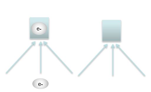
Distributing individual photo-electrons into a separate independent amplification micro-channel
Amplification
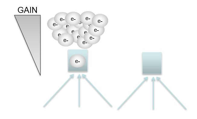
Amplifying each individual photo-electron through a separate micro-channel into a readable charge packet
Reading
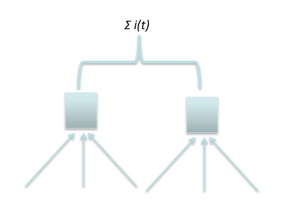
Recovering the amplified charge packets by integrating the output of all micro-channels
This special 3-function design provides a unique photodetector: one that incorporates and combines the best of avalanche, as well as Geiger-mode photodetectors. The Geiger mode operation contributes to the ability to detect single photons, whereas the multi-channel design provides always on availability, and the ability to respond in a proportional manner to the number of detected photon, which are distributed among the many channels.
The negative feedback mechanism that is realized with these three functions (distribution, amplification and reading) delivers a photon detector with unique characteristics:
- Single and multi photon detection ability
- linear response to number of photons
- Each micro-channel has a fast recovery time
- No ‘dead time’, as active cells do not affect their neighbors
- Simpler electronic signal extraction due to the large charge packet which is generated as a response to a single photon
- Subsequent digital signal processing simplification, as one does not need to built histograms
Proportional Response to The Number of Photons
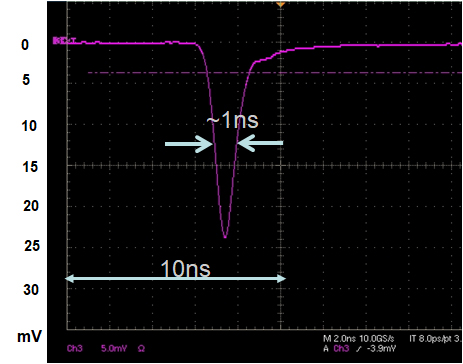
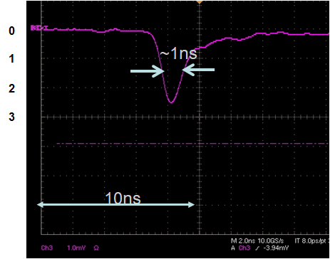
An example response of a DAPD to a 800-photon pulse directly on an oscilloscope (left) and 20- photon pulse (right). The 20-photon response is 3mV high, whereas the 800-photon response is 24mV high
Details:
To eliminate electronic amplifier saturation, this measurement is performed without a pre-amplifier, directly connecting the DAPD to an oscilloscope. The circuit used comprises of AC coupling using a 10nF capacitor. The illumination level captured in these two examples is: Left 818 photon/pulse. Right 20 photons/pulse. The scan shows averaging over 100 wave-fronts (pulses). The pulse height is 24mV or 2.5mV, pulse width at Full Width Half Maximum (FWHM) is approximately 1ns in both examples, as there is no broadening of the response to a larger number of photons.
Example
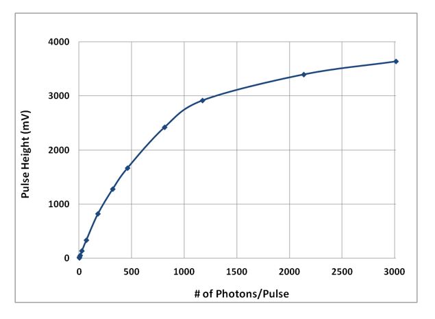
Calibrated Laser source response of a 200µm-aperture DAPD to varying pulse energy
Details:
As seen in the previous example, pulse height varies as the energy of the detected pulse, in a proportional manner. In this example, a pre-amplifier was used to increase the height of the DAPD output. The DAPD in this example has 250micro-cells, and approximately 20% Single-Photon Detection Efficiency (PDE). Hence the observed ~1250 photons/pulse “knee”, where saturation begins. Note the unique ability of the DAPD to respond to higher than the satuaration level of photons. For example: the response signal for 3000 photons/pulse is ~3700mV , where the saturation level (1250 Photons/pulse )signal level is 2900mV.
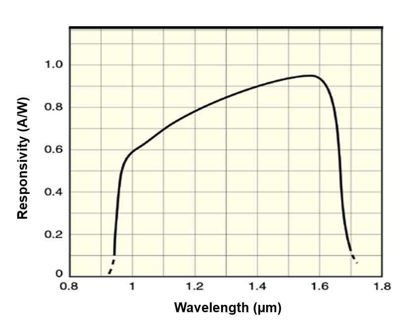
Spectral Response of DAPD at 23°C; Gain=~1
